Single Channel Ultrasonic Water Meter
- Introduction
- Picture
- Specification
- Download
- Installation Video
- Inquiry
Name:Ultrasonic Water Meter
Model:LRF-2000W
General Introduction:
The highly integrated LRF-2000W ultrasonic water meter is designed and manufactured strictly according to GB/T778.1-2007, ISO4064-1:2005 etc., based on ultrasound transit-time measurement technology.
ultrasonic water meter has wired type as standard configuration, wireless type need to be customized.
Features:
● compact, all plastic,IP68 protection grade
●100:1 range ratio with high accuracy
●pipeline integrated probe, not easy to produce scaling
●ultrasonic signal is adaptive to measure water containing impurities
●single chip SOC digital time-difference processing
●multi-line display with status, touch buttons operation
●optional built-in Lora or NB-iot function
●RS485 and MBUS dual interfaces
●multi-communication protocols like MODBUS,MBUS,and CJ188
●external power supply can be connected
●built-in battery of 10 years service life
●reliable and low price ,suitable for mass applications
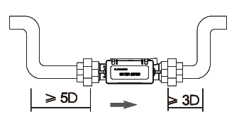
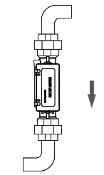
Choose the installation point:
| Correct installation point | Wrong installation point | ||
 |
.png) |
.png) |
 |
| Lowest point of the pipe line, water will be full of pipe.
Flow is vertically or obliquely upward.
Upstream straight pipe line≥5D.
|
Highest point of the pipe line, water would be not full of pipe.
Flow is vertically or obliquely downward.
Upstream straight pipe line≤3D.
|
||
Flow Rate:
| Nominal Diameter |
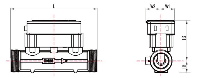
Flow Meter Dimension | Thread Dimension | Weight | ||||||
| L | H1 | H2 | W1 | W2 | Thread standard |
Thread Length |
Thread Standard |
||
| DN15 | 165 | 15 | 71 | 25 | 28 | G3/4 | 11 | GB/T7307 | 0.7 |
| DN20 | 130 | 19 | 73 | 25 | 28 | G1 | 13 | 0.7 | |
| DN25 | 160 | 22 | 76 | 25 | 33 | G1 1/4 | 14 | 0.9 | |
| DN32 | 180 | 25 | 78 | 25 | 37 | G1 1/2 | 14 | 1.1 | |
| DN40 | 200 | 34 | 82 | 30 | 37 | G2 | 16 | 1.6 | |
| Nominal Diameter (mm) |
Measurement Range Rayio R |
Flow Rate(m³/h) | ||||
| Starting Flowrate |
Minimum Flowrate Q1 |
Transitional Flowrate Q2 |
Permanent Flowrate Q3 |
Overload Flowrate Q4 |
||
| DN15 | 200 | 0.003 | 0.013 | 0.020 | 2.500 | 3.125 |
| DN20 | 200 | 0.004 | 0.016 | 0.026 | 3.200 | 4.000 |
| DN25 | 100 | 0.010 | 0.040 | 0.064 | 4.000 | 5.000 |
| DN32 | 100 | 0.016 | 0.063 | 0.101 | 6.300 | 7.875 |
| DN40 | 100 | 0.050 | 0.200 | 0.320 | 20.000 | 25.000 |
Transmitter:
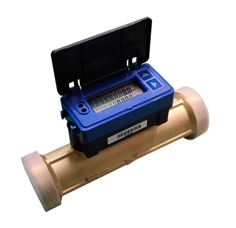
.png)
Window:
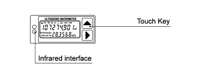
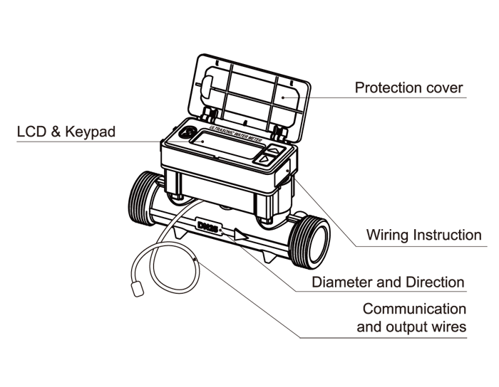
Front View of Wired Type Water Meter:
Size:
| Performance | Parameters |
| Working Pressure | 2.5 MPa |
| Temperature | T30 |
| Working Environment | -25℃~55℃,IP68 Protection |
| Pressure Loss | △P63 |
| Display Range | Multi-lines show 9-bit cumulative flow,6-bit instaneous flow,signal strength |
| flow direction,error,communication status | |
| Unit | m³,USG,Liter,cubic foot,Acre Feet |
| Operating Mode | Two capacitive touch keys support sliding operation. |
| Communication Interface | Physically independent RS485 and infrared interface.LORA/NB-IOT,WIFI,USART are optional. |
| Output | 2 way of OCT output is optional,can simulate dipulse output of mechanical water meter. |
| Communication Protocol | MBUS,MODBUS,ASCLL,CJ188 |
| Power Supply | 3.6V 4Ah lithium battery(battery life>10 years).It will operate power save functions when there is no water and flow in pipe |
| DC12~30V external power supply through MBUS interface;data will be permanently saved after power off. | |
| Power consumption | <0.1mW |
| Material | Pipe body:copper;others;PEEK |

